


+ AudioBridge: From sound to vision
Summary
AudioBridge is a hybrid digital Eurorack module
that turns any incoming audio into expressive
control voltage and retro-styled graphics.
At its core sits a Teensy 4.0 running a high-
resolution FFT engine. Your audio is continuously
analysed and split into four frequency bands,
each converted into a smooth, fast CV output.
Drums, melodies, textures—anything you
feed it—instantly become modulation sources.
In parallel, a Raspberry Pi Pico 2 drives
a dedicated visual engine. It listens to the
same FFT data stream and generates vibrant,
old-school computer-style animations that move
and react to your sound in real time.
Think spectrum bars, geometric patterns,
rhythmic pulses-digital nostalgia shaped by
your audio.
The result is a module that bridges audio,
control voltage, and motion graphics into a
single creative tool.
Specs
- 3U/12HP = approx. H129mm x W61mm
- Depth approx. 35mm
- +12V = 125mA, -12V = 0mA, +5V = 0mA
- 2 x Rotary Encoder - control (turn and press)
- 1 x toggle switch - lock frequency pan
- 1 x Dial - audio sensitivity
- 1 x Full Colour 128x128px TFT screen
- 1 x Audio in (ST/M) + 1 x Audio Thru
- 1 x HDMI Out (320x240)
- 4 x CV out
Demos
Live jam from The Mashed Swedes, with the AudioBridge module driving the audio-reactive graphics in the background. The projector is running visuals straight from the module’s HDMI output, reacting in real time to the mix. Enjoy the synths, the glitches, and the pixels.
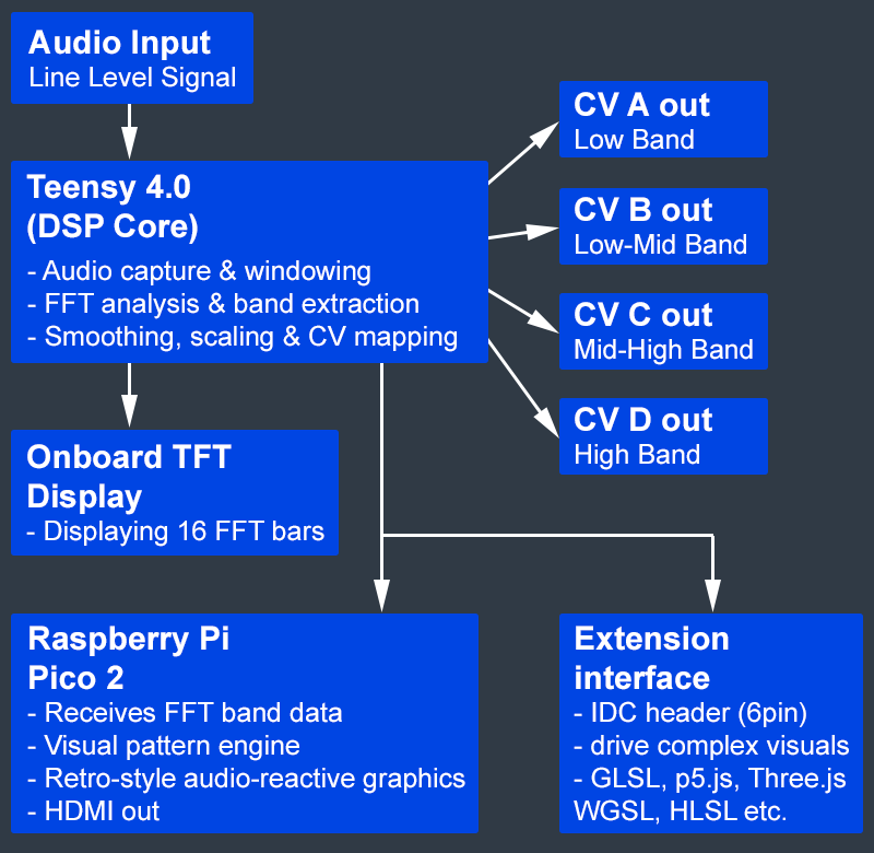
The AudioBridge Signal Flow
AudioBridge takes any incoming audio signal and transforms it into both expressive
control voltages and vibrant visual output. The Teensy 4.0 DSP core performs the
heavy lifting - capturing audio, analysing it with FFT, and extracting four musical
frequency bands. These become the module’s CV outputs: Low, Low-Mid, Mid-High,
and High.
In parallel, the Pico 2 receives the same spectral data to generate retro-style
audio-reactive graphics, which can be displayed on the onboard TFT or sent out
via HDMI. An extension interface allows creatives to build their own visual
engines using GLSL, p5.js, Three.js, WebGPU (WGSL), HLSL, and more.
Front Panel (Quick Guide)
Download the AudioBridge Visual Summary / Quick guide (PDF | 13Mb) here
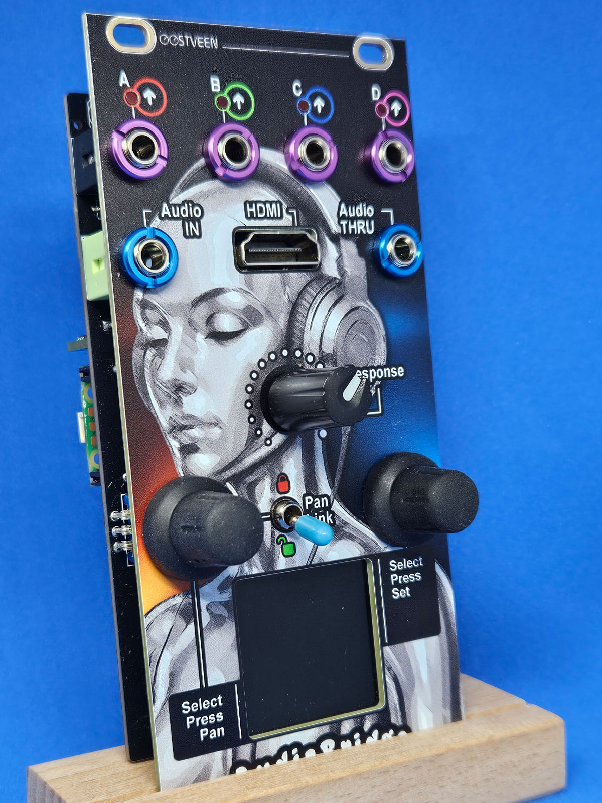
The Front Panel
The AudioBridge front panel, shown below, is organized into four sections.
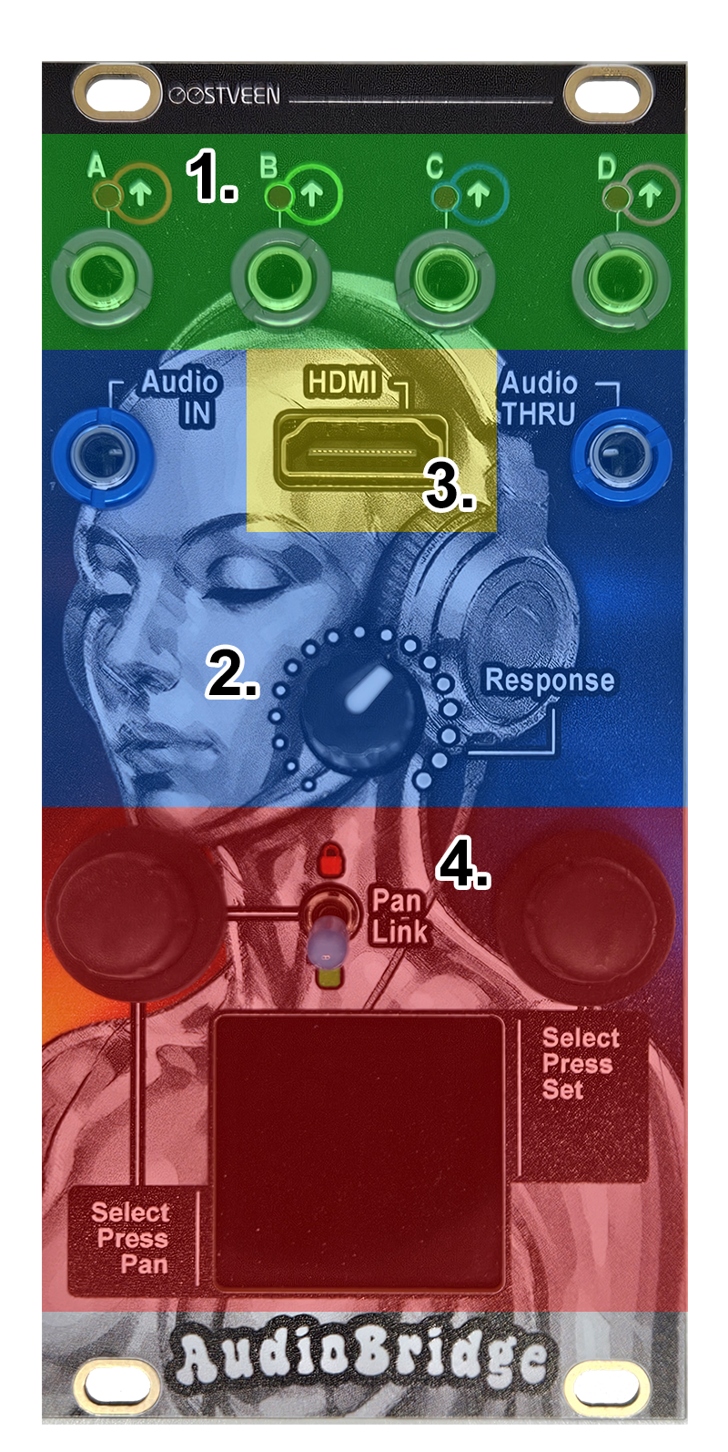
- 4 x Control Voltage Out + 4 x LED
Each of the four control-voltage outputs corresponds to a frequency band (A, B, C, and D). Each band represents the average of four frequency spectra within that range. Output voltage varies between 0 and 5V. - Audio
The AudioBridge module accepts either a mono or stereo signal at the Audio In jack. The input signal can be passed on to other modules through the Audio Thru output. The Response dial adjusts the input level used for FFT analysis (essentially the height of the FFT bars on the display) - HDMI
AudioBridge includes an HDMI (High-Definition Multimedia Interface) output, which is uncommon in Eurorack modules. The onboard Raspberry PI Pico 2 generates a 320×240 video signal that’s sent directly over HDMI, allowing the module to feed a monitor, capture device, or video mixer without any adapters or extra hardware. - 2 x Encoder/Push Button + Toggle Switch
The left and right encoders are used to navigate the module’s menus. The toggle switch provides quick locking and panning of the A, B, C, and D frequency bands. The menu system, including the toggle switch functions, is covered in the AudioBridge Menus section.
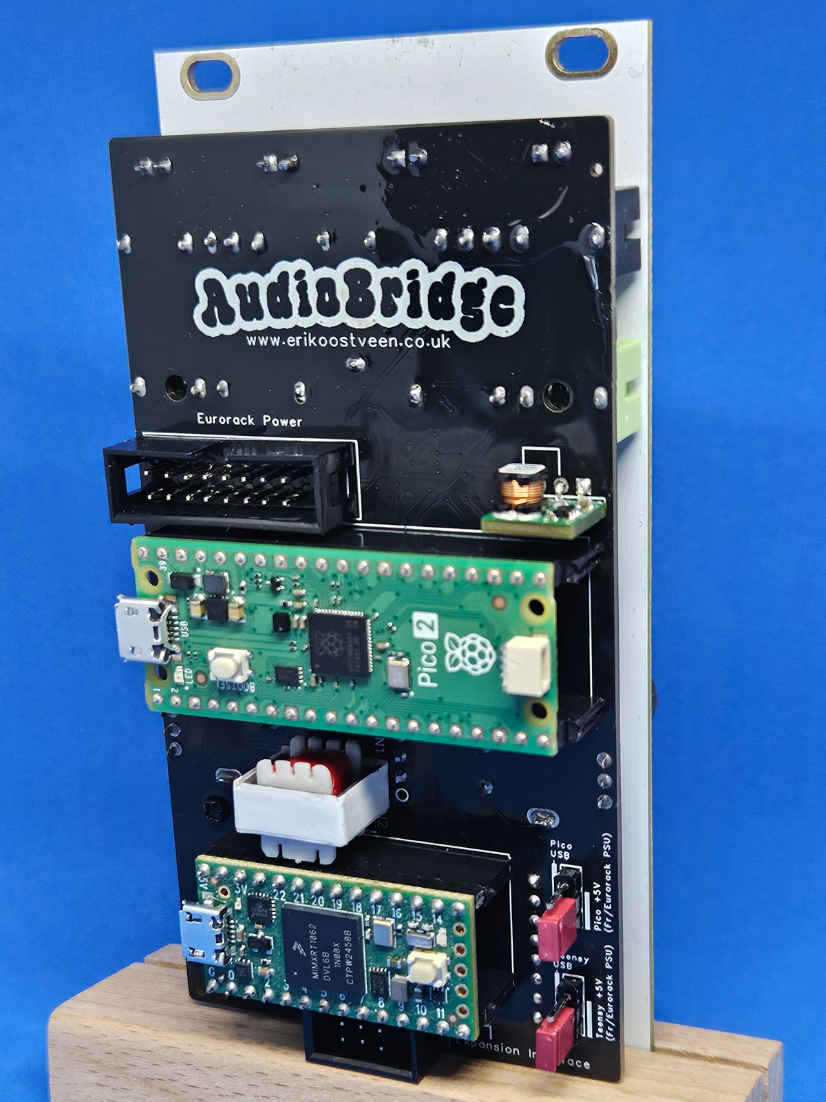
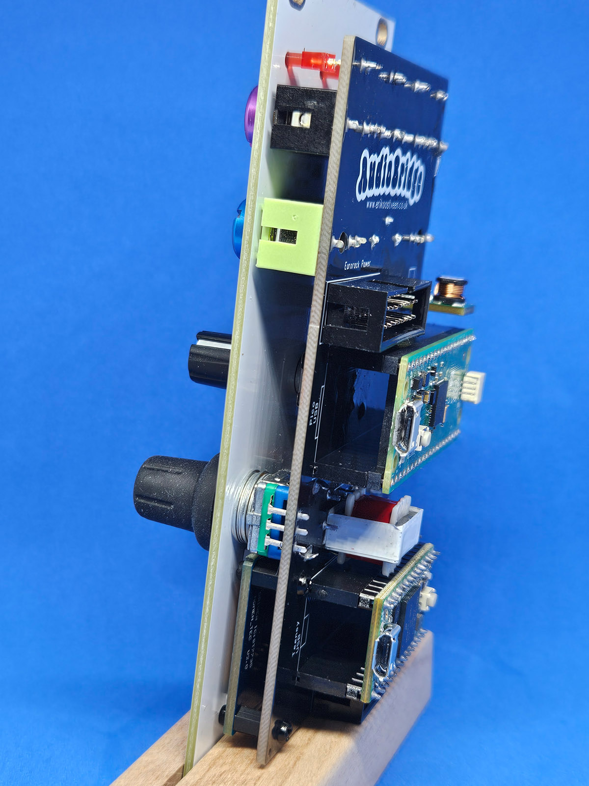
Rear of the Module
Shown below is the AudioBridge's rear view.
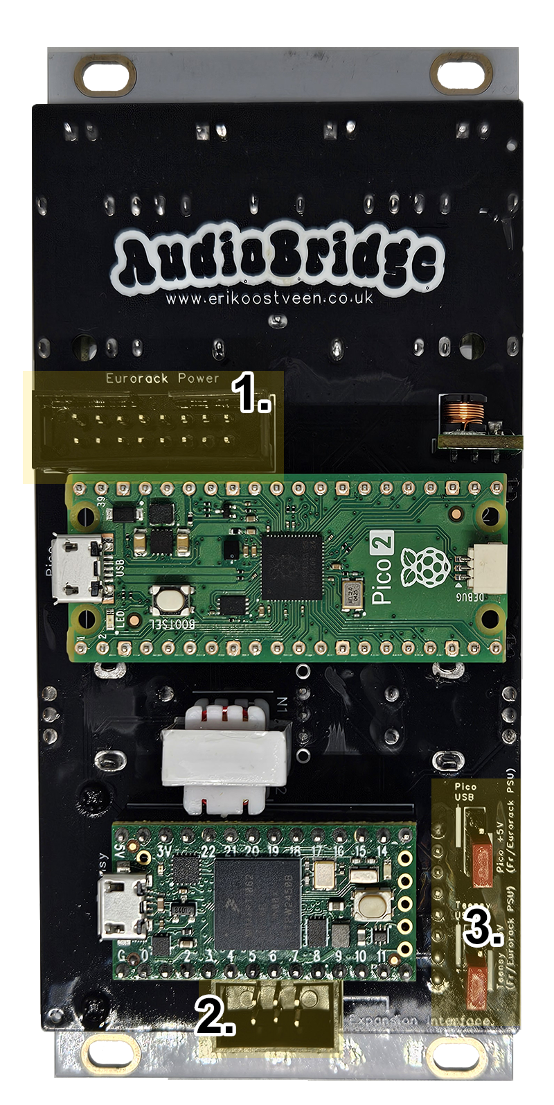
- Eurorack Power
Connect the module to your case’s bus board using the Eurorack power header, aligning the ribbon cable’s red stripe with the pin marked ‘1’ in the image. - Extension interace
The extension header is reserved for future expansion. It provides an interface for a planned companion module focused on 3D visuals, such as GLSL-based shaders, p5.js graphics, Java rendering pipelines, and similar real-time visual engines. - Jumpers (2x)
These two jumpers let you disconnect the Teensy and Pico 2 development boards from the Eurorack power supply. This is useful when developing or uploading new firmware. Under normal use, keep both jumpers installed as shown in the image above.
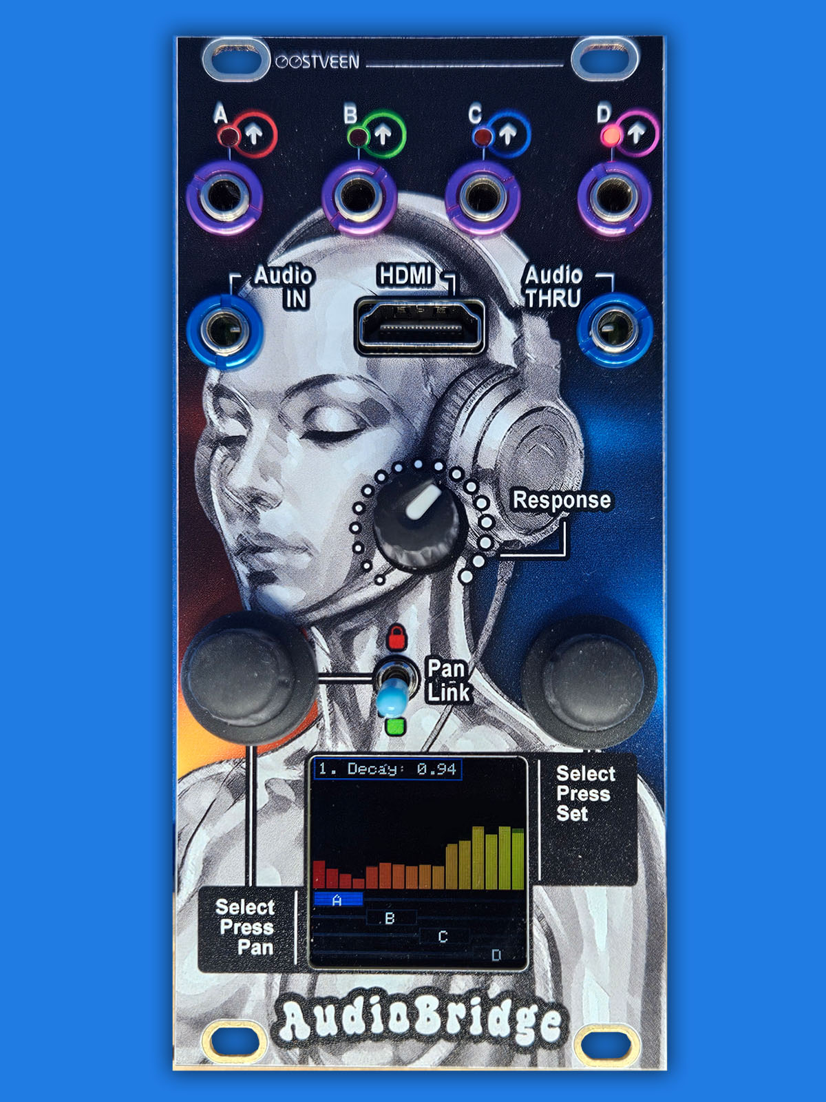
AudioBridge menus
AudioBridge has eleven menus, which you navigate by turning the right encoder. The available menus are listed below and described in detail in the following sections.
1. Decay (0.00 = No decay, 0.99 = Slow | Def.: 0.85)
2. Attack (0.00 = No Attack, 0.99 = Slow | Def.: 0.50)
3. Input Gain (0.0 = muted, 1.0 = max) | Def.: 1.0)
4. FX: 1/40 (1-35 & 36-40 | Def.: 1)
5. Layout: 1/256 (1-256 | Def.: 1)
6. Gain Tx A (0.0 = muted, 1.0 = max) | Def.: 1.0)
7. Gain Tx B (0.0 = muted, 1.0 = max) | Def.: 1.0)
8. Gain Tx C (0.0 = muted, 1.0 = max) | Def.: 1.0)
9. Gain Tx D (0.0 = muted, 1.0 = max) | Def.: 1.0)
10. Theme: 1/50 (1-50 | Def.: 1)
11. Source (Audio In, Test 1-3) | Def.: 1
Note that when powered on, AudioBridge loads the last menu settings you used.
The right Encoder
- Decay
Use the right encoder to navigate to "1. Decay" and press it. The inner box around the menu text will flash, indicating that the encoder is now locked to this parameter. Turn the encoder to set how fast the FFT bars fall. A slower decay produces smoother visual motion that’s easier to follow on the display. The 4 x CV out is also affected by this setting. Press again to unlock. - Attack
Use the right encoder to navigate to "2. Attack" and press it. The inner box around the menu text will flash, indicating that the encoder is now locked to this parameter. Turn the encoder to set how fast the FFT bars rise. A slower attack produces smoother visual motion that’s easier to follow on the display. The 4 x CV out is also affected by this setting. Press again to unlock. - Input gain
Use the right encoder to navigate to "3. Input Gain" and press it. The inner box around the menu text will flash, indicating that the encoder is now linked to this parameter. Input Gain lets you boost or reduce the incoming audio level. The default value is 1.0. When this setting is anything other than 1.0, the FFT bars are underlined with a purple line to indicate the adjustment. The 4 x CV out is also affected by this setting. Press again to unlock. - FX
Use the right encoder to navigate to "4. FX: 1/40" and press it. The inner box around the menu text will flash, indicating that the encoder is now linked to this parameter. Choose an audio-reactive visual (1–39), a test screen (36–39), or, (40), let AudioBridge pick a random audio-reactive visual (1–35) every 8 to 30 seconds. When you select a visual, it takes about two seconds for the module to switch to the chosen effect. Note that each visual’s name includes a label such as (A–D), (E–T), or (A). This indicates which FFT values drive the visual: the four band values A–D, all sixteen FFT bars E–T, or a single value such as A. Press again to unlock. - Layout
Use the right encoder to navigate to "5. Layout: 1/256" and press it. The inner box around the menu text will flash, indicating that the encoder is now linked to this parameter. Turn the encoder to reposition the A, B, C, and D boxes under the FFT bars. There are 256 possible layouts. Changing the layout also changes how the four CV outputs respond. For example, layout 29 assigns all CV outputs to the first four FFT bars (bass range). The layout menu offers a quick way to move these boxes, and we’ll cover more precise control later when discussing the left encoder. Press again to unlock. - Gain Tx A
Use the right encoder to navigate to "6. Gain TX A" and press it. The inner box around the menu text will flash, indicating that the encoder is now linked to this parameter. Turn the encoder to boost or reduce the average transmitted value for A. The default value is 1.0. When this setting is anything other than 1.0, the horizontal line underneath the A box turns red to indicate the adjustment. This value change affects CV output A. Note that because this parameter is derived from the FFT bars, adjusting the Tx value does not affect the on-screen bars. Press again to unlock. - Gain Tx B
Use the right encoder to navigate to "7. Gain TX B" and press it. The inner box around the menu text will flash, indicating that the encoder is now linked to this parameter. Turn the encoder to boost or reduce the average transmitted value for B. The default value is 1.0. When this setting is anything other than 1.0, the horizontal line underneath the B box turns red to indicate the adjustment. This value change affects CV output B. Note that because this parameter is derived from the FFT bars, adjusting the Tx value does not affect the on-screen bars. Press again to unlock. - Gain Tx C
Use the right encoder to navigate to "8. Gain TX C" and press it. The inner box around the menu text will flash, indicating that the encoder is now linked to this parameter. Turn the encoder to boost or reduce the average transmitted value for C. The default value is 1.0. When this setting is anything other than 1.0, the horizontal line underneath the C box turns red to indicate the adjustment. This value change affects CV output C. Note that because this parameter is derived from the FFT bars, adjusting the Tx value does not affect the on-screen bars. Press again to unlock. - Gain Tx D
Use the right encoder to navigate to "9. Gain TX D" and press it. The inner box around the menu text will flash, indicating that the encoder is now linked to this parameter. Turn the encoder to boost or reduce the average transmitted value for D. The default value is 1.0. When this setting is anything other than 1.0, the horizontal line underneath the D box turns red to indicate the adjustment. This value change affects CV output D. Note that because this parameter is derived from the FFT bars, adjusting the Tx value does not affect the on-screen bars. Press again to unlock. - Theme
Use the right encoder to navigate to "10. Theme: 1/50" and press it. The inner box around the menu text will flash, indicating that the encoder is now linked to this parameter. Turn the encoder to pick an FFT bar colour scheme that tickles your fancy. This settitng doesn't affect anything else. Press again to unlock. - Source
Use the right encoder to navigate to "11. Source" and press it. The inner box around the menu text will flash, indicating that the encoder is now linked to this parameter. Source lets you choose either the module’s Audio In signal (menu option: Audio In) or, if no external audio is present, one of three internal test signals:
Test 1 - Sinewave
Test 2 - Random sweeping band, consisting of four frequency slices
Test 3 - Music simulation
These test signals are useful when setting up a screen or projector connected to the AudioBridge module - or for developing new visuals.
Press again to unlock.
The left Encoder + toggle switch
- Panning
Turn the encoder to highlight one of the four bands (A,B,C or D) and press it. An outer box around the band-box will flash, indicating that the encoder is now linked to this parameter. Turning the encoder again lets to reposition the selected box. Like the Layout menu #5 but more precise. Press again to unlock. - Toggle Switch Align Lock/Unlock
The toggle switch lets you align all boxes at once (up position) and pan them using the encoder. In this mode, all four CV outputs move together and are affected in the same way.